Orientation Tracking (Click Here!)
Full code can be provided upon request
Introduction
Robotic autonomy hinges on four core components: localization, planning, mapping, and control. This project focuses on localization, specifically tracking the orientation of a camera equipped with an IMU (Inertial Measurement Unit) over time. The project’s goal includes validating this approach using VICON motion capture data as ground truth and creating a 3D panorama from the captured images to further verify the results.
Problem Formulation
Orientation Tracking
The objective is to track the orientation of a camera using IMU data. The IMU provides linear acceleration and angular velocity data, which, along with quaternion kinematics, is used to predict the camera’s orientation over time. The goal is to estimate the orientation trajectory using a motion model and an observation model that takes gravity into account.
Panorama
The project also aims to generate a panoramic image by stitching together the camera images based on the estimated orientation. This involves calculating the orientation at each timestamp and using this to align the images correctly.
Technical Approach
Sensor Calibration
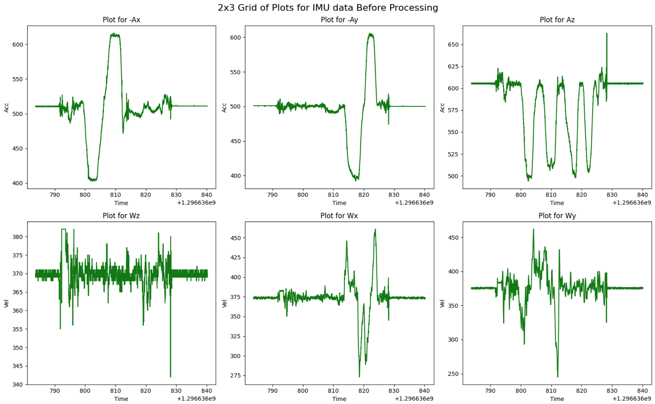
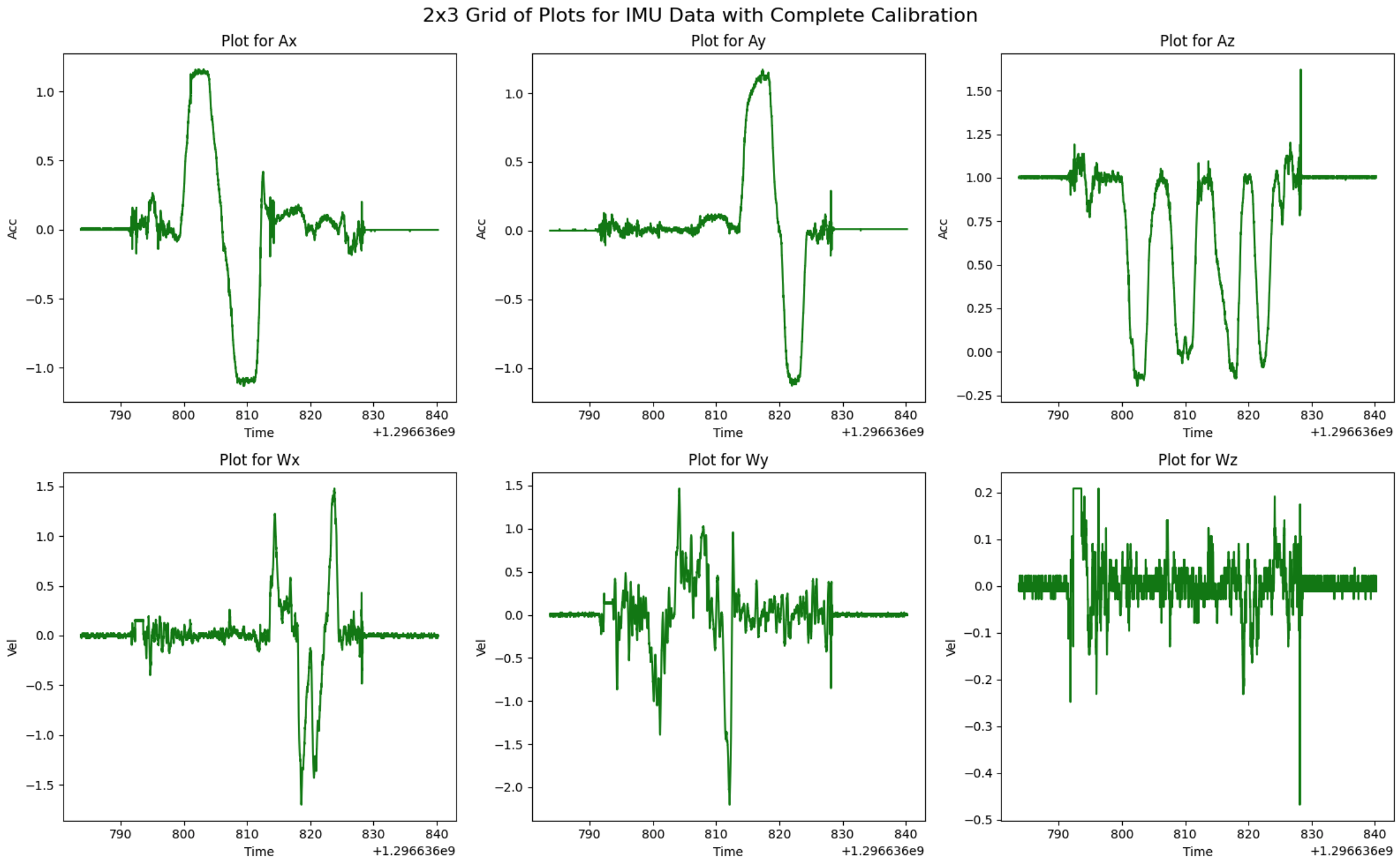
Before processing the data, it’s essential to calibrate the IMU to correct known biases and errors, such as flipped axes and incorrect angular velocity ordering. The IMU data is adjusted using scale factors and biases derived from sensor datasheets and VICON data. After calibration, both the IMU and VICON data are visualized to ensure accuracy.
- Figure 1: IMU Data before Processing.
- Figure 2: IMU Data after Processing.
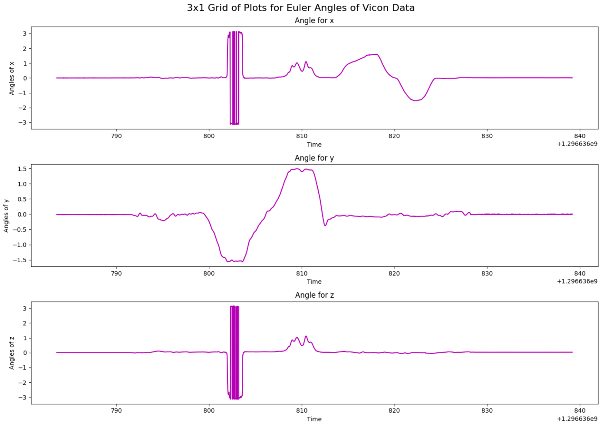
- Figure 3: Euler Angles of VICON.
Orientation Tracking
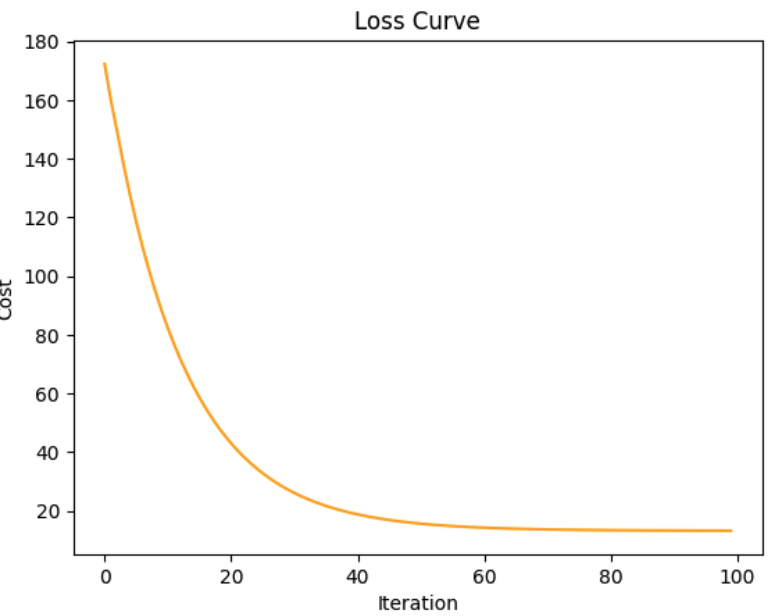
Orientation tracking is achieved through a cost function that combines the motion model and the observation model. The initial trajectory is estimated, then refined using a constrained gradient descent algorithm. The results are compared against the VICON data to validate the estimates.
Figure 4: Motion Estimate Vs. VICON (Initial).
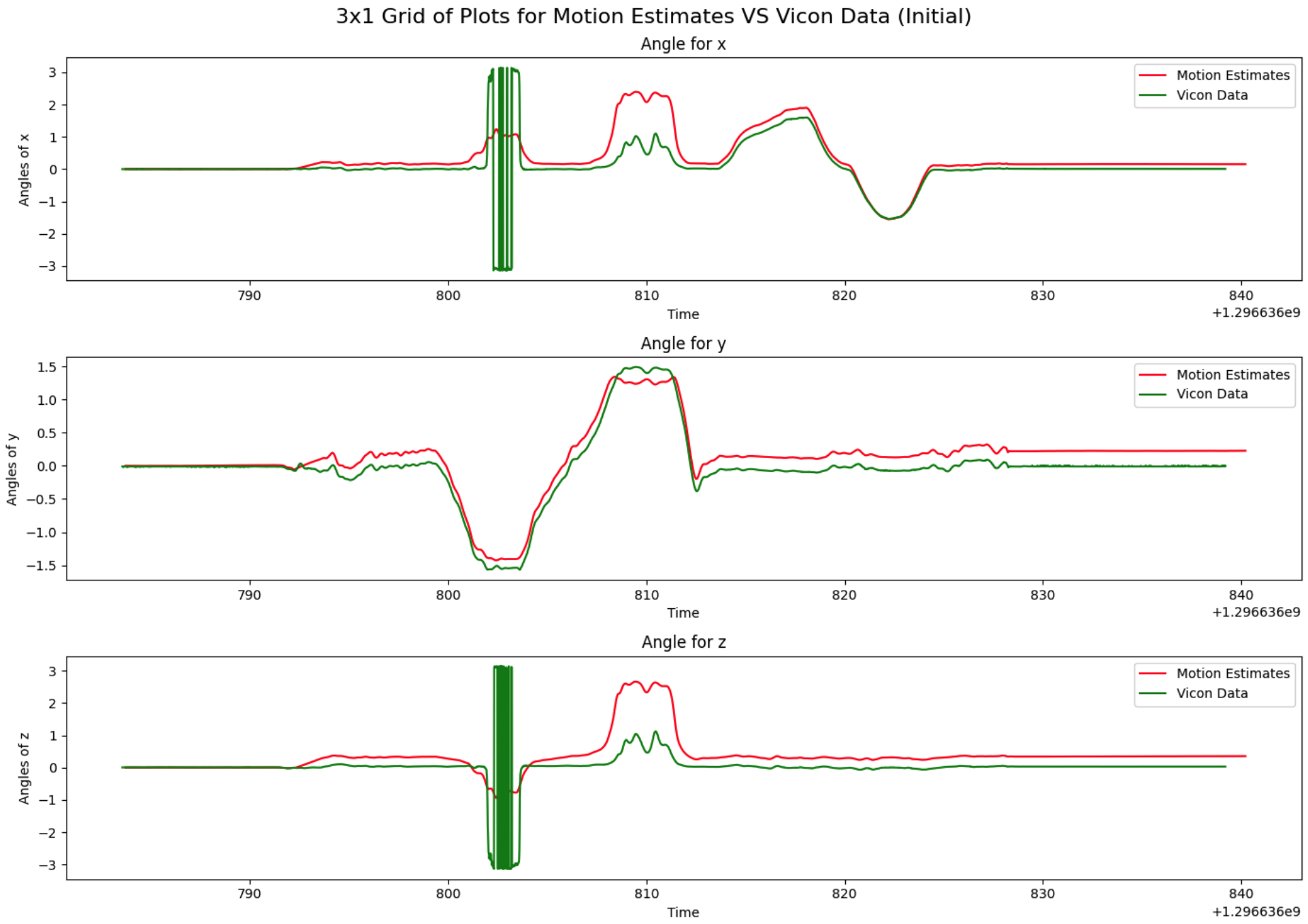
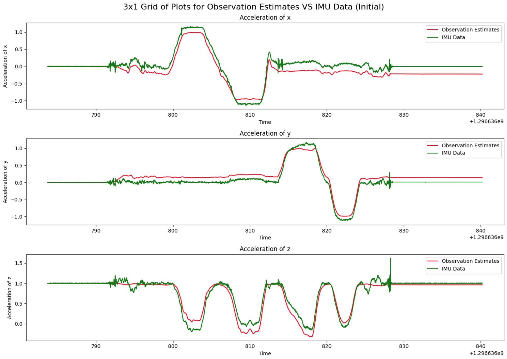
Figure 5: Observation Estimate Vs. Accelerometer (Initial).
Panorama
Once the orientation is tracked, the next step is constructing a panoramic image. This involves converting pixel coordinates to spherical coordinates, rotating these according to the estimated orientation, and then mapping them back to an image. The resulting panorama visually represents the camera’s field of view over time.
Results
Orientation Tracking
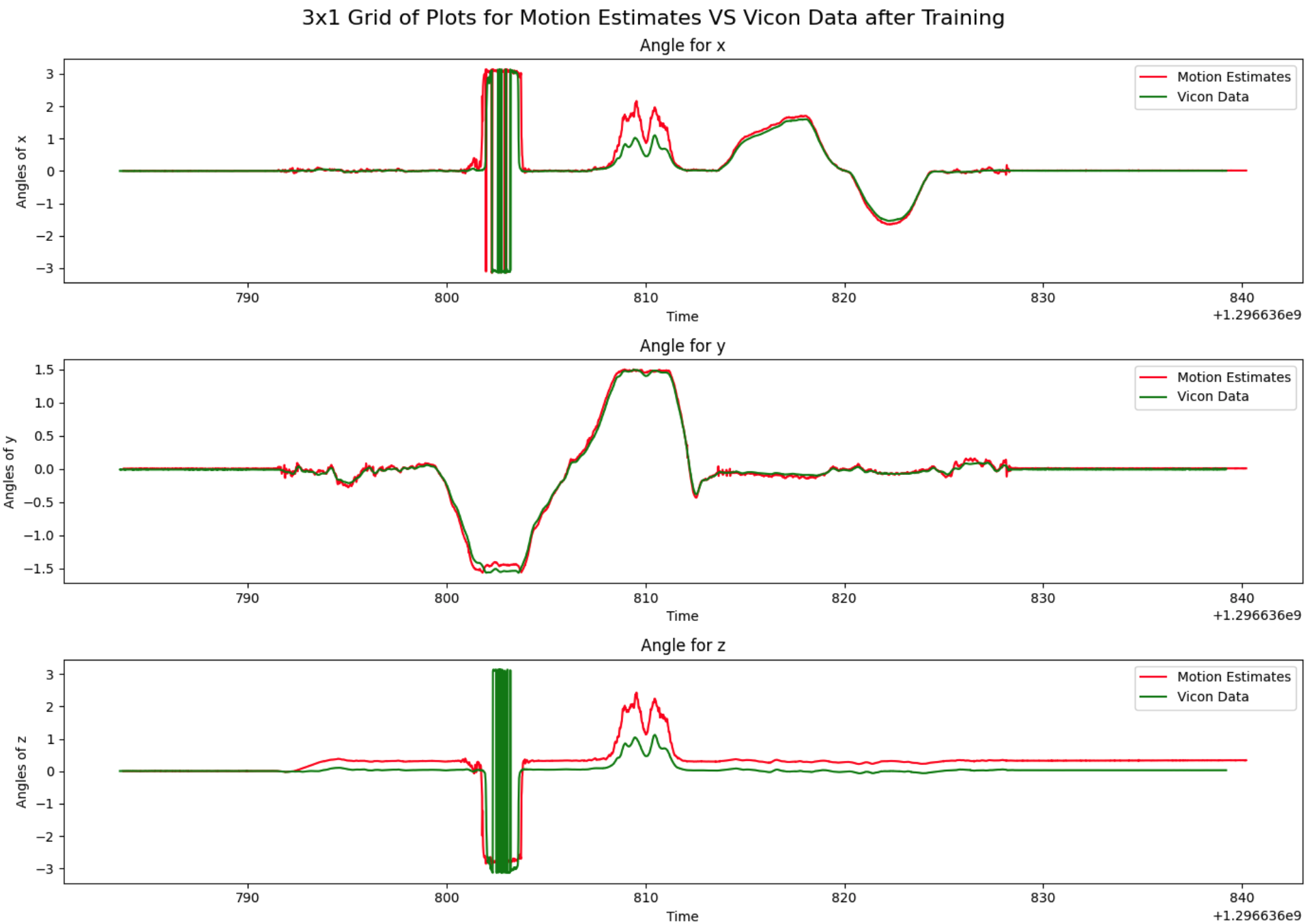
The final orientation estimates show a significant improvement after optimization, closely matching the VICON data. However, in some datasets, especially those with an IMU reset glitch, there is an offset in the yaw angle that remains after training.
Figure 6: Motion Estimate Vs. VICON (Final).
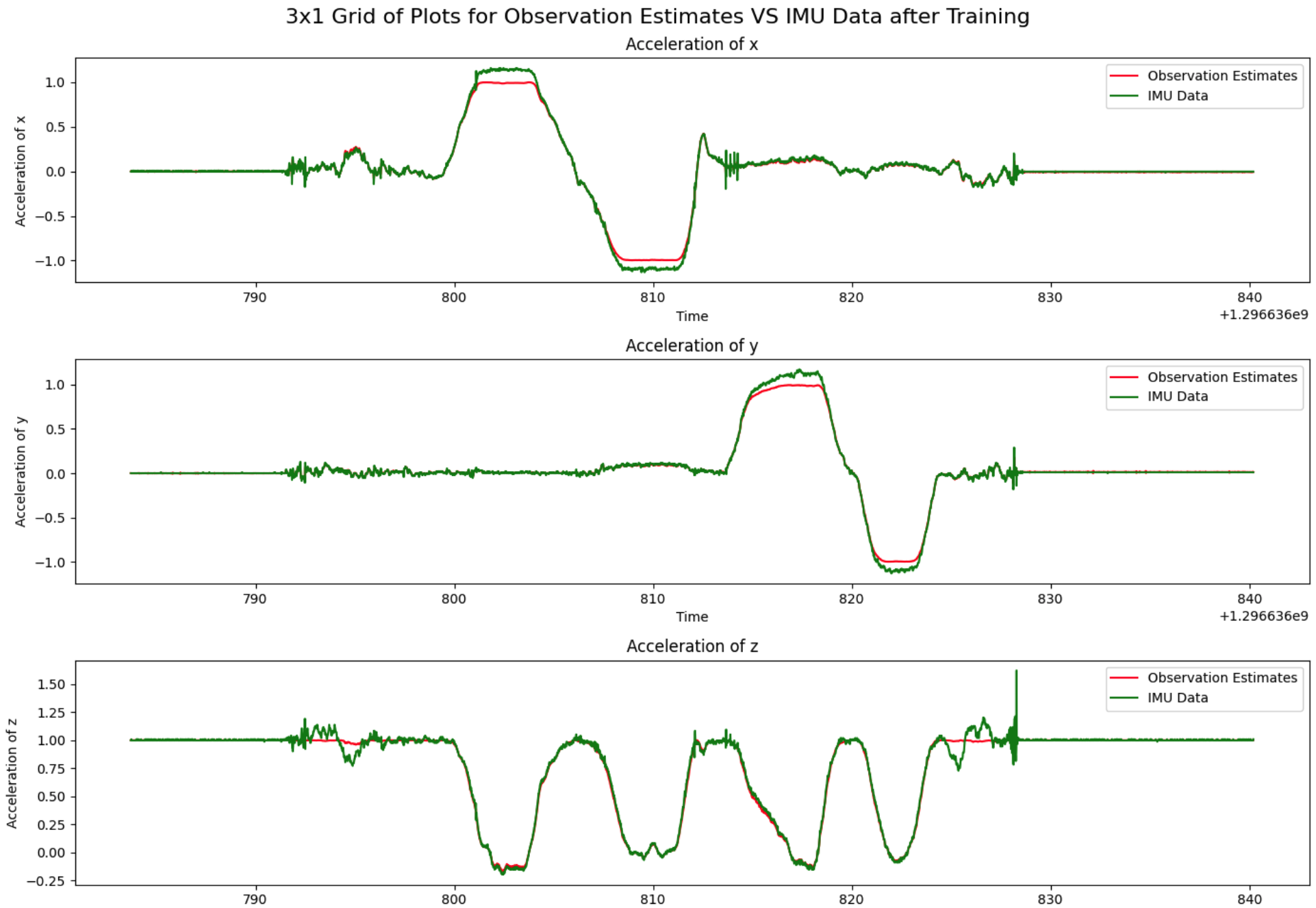
- Figure 7: Observation Estimate Vs. Accelerometer (Final).
- Figure 8: Loss Curve.
Panorama
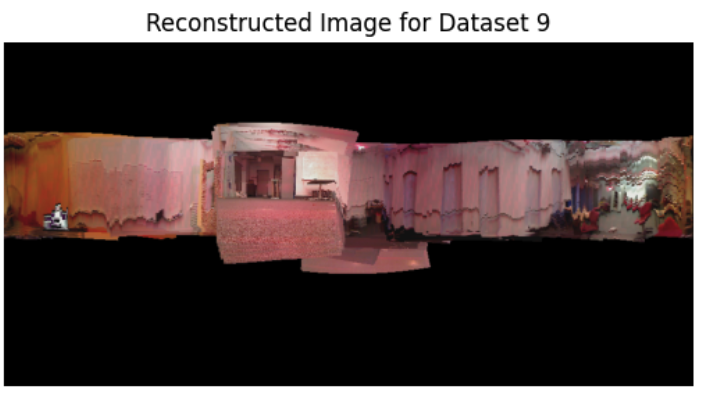
The generated panoramic image gives a reasonable representation of the captured environment, although some datasets exhibit distortions likely due to camera tilt.
- Figure 9: Final Panoramic.